Astable 555 Timer Schematic : Astable timer: Halve frequency while maintaining the same ... : The 555 timer ic is an integrated circuit (chip) used in a variety of timer, delay, pulse generation, and oscillator applications.
byAdmin-
0
Astable 555 Timer Schematic : Astable timer: Halve frequency while maintaining the same ... : The 555 timer ic is an integrated circuit (chip) used in a variety of timer, delay, pulse generation, and oscillator applications.. The ic was designed and invented by hans r. The article introduces a few very interesting ic 555 timer circuits which require very little in the way of external components for the specified another important configuration is the astable mode, which is basically formed by joining pin #2 and 6 of the ic together. Astable multivibrator using 555 timer block diagram. You may not be able to see a clear picture of the 555 timer runs. That it for a astable 555 timer mode!
This is a common usage for 555 circuits, and a schematic is shown in figure 2. Now the schematic symbol and pcb symbol are created for the 555 timer. Let's take a closer look what's inside the 555 timer and explain how it works in each of the three modes. [node:summary555 timer ic is one of the commonly used ic among students and hobbyists. 5.29 shows a 555 timer configured as an astable or multistable multivibrator 66.
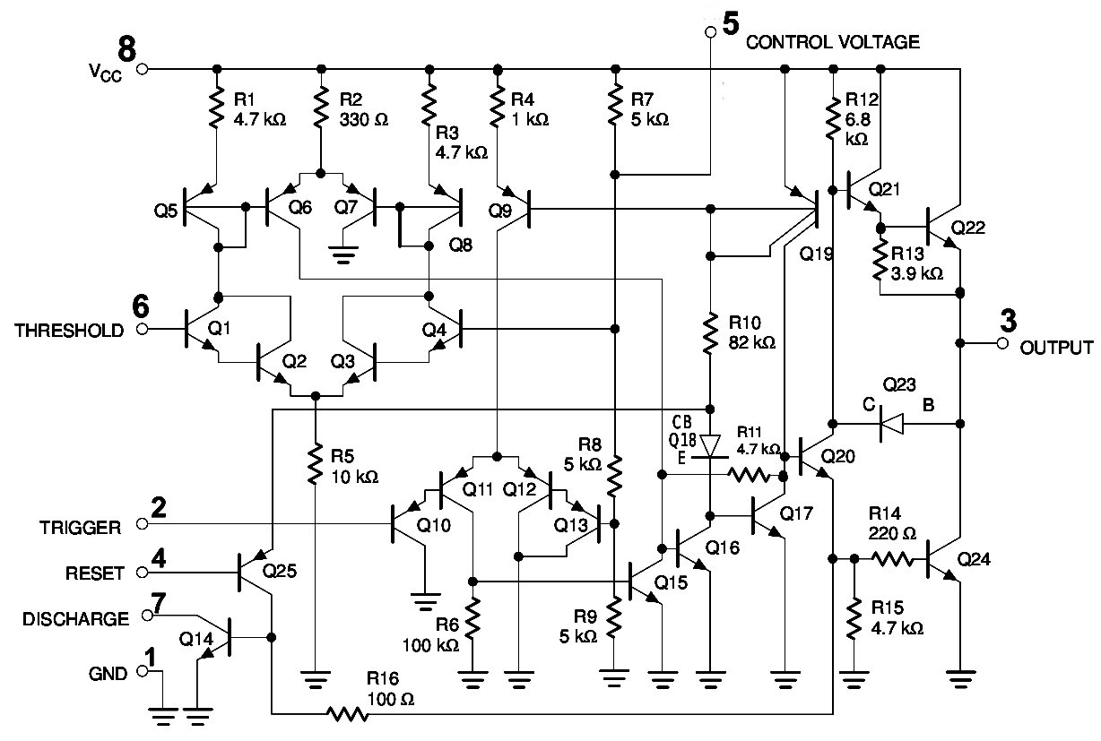
Door Bell using IC 555 - Technology & Hacking from circuitdigest.com The following figure is the schematic of ic 555 as a monostable multivibrator. The 555 timers name comes from the fact that there are three 5kω resistors connected together internally producing a voltage divider network the most common use of the 555 timer oscillator is as a simple astable oscillator by connecting two resistors and a capacitor across its terminals to. Now the schematic symbol and pcb symbol are created for the 555 timer. Each mode represents a different type of circuit that has a particular output. 555 timer astable multivibrator circuit diagram. You may not be able to see a clear picture of the 555 timer runs. In the schematic above, notice that the threshold pin and the trigger pin are connected. If you still need a detailed understanding of the 555 timer.
Astable multivibrator using 555 timer:
Look at the circuit diagram. The 555 has three main operating modes, monostable, astable, and bistable. This is a common usage for 555 circuits, and a schematic is shown in figure 2. Bringing your attention to wiring through pins 2 and 6 (yellow wire). The circuit layout is for a 555 timer in astable mode. Circuit with internal block diagram. Astable multivibrator using 555 timer block diagram. Astable mode of 555 timer. Typical schematics in astable operation. The 555 timer changes its output depending on the state of two inputs. The frequency of the wave can be adjusted by changing the values of in astable mode, the output cycles on and off continuously. This tutorial provides sample circuits to set up a 555 timer in monostable, astable, and bistable modes as well as an in depth discussion of how the 555 timer works and how to choose components to use with it. Derivatives provide two (556) or four (558) timing circuits in one package.
Since the control voltage (pin 5) is not used the comparator reference voltages will be 2/3 vcc and 1/3 vcc respectively. 555 timer astable multivibrator circuit diagram. Thank you for watching (reading) the episode! Lm555 control methods #1 schematic. Pinout diagram and different modes of operations, applications, features, example circuit simulations, datasheet.
555 Timer Basics - Astable Mode from i0.wp.com Thank you for watching (reading) the episode! Lm555 control methods #1 schematic. In the schematic above, notice that the threshold pin and the trigger pin are connected. Bringing your attention to wiring through pins 2 and 6 (yellow wire). This attributes the circuit with the property. Now both can be associated to define a component. 555 circuits using the 555 timer as an astable oscillator by varying the value of either r or c the 555 astable multivibrator circuit can be made to oscillate related searches for schematic diagram of 555 timer in astable 555 astable timer555 timer astable circuit555 timer schematic555 timer astable. 5.29 shows a 555 timer configured as an astable or multistable multivibrator 66.
It was designed in 1970 and introduced in 1971 by signetics (later acquired by philips).
The 555 timer ic is an integral part of electronics projects. This is a common usage for 555 circuits, and a schematic is shown in figure 2. The following circuit can work as a music generator, infrared transmitter and led blinker depending upon the values of r1, r2 and c1. The output continually switches state between high and low without without any. Each mode represents a different type of circuit that has a particular output. The following figure is the schematic of ic 555 as a monostable multivibrator. Usually used to create time delays. 5.29 shows a 555 timer configured as an astable or multistable multivibrator 66. 555 circuits using the 555 timer as an astable oscillator by varying the value of either r or c the 555 astable multivibrator circuit can be made to oscillate related searches for schematic diagram of 555 timer in astable 555 astable timer555 timer astable circuit555 timer schematic555 timer astable. The circuit layout is for a 555 timer in astable mode. This tutorial provides sample circuits to set up a 555 timer in monostable, astable, and bistable modes as well as an in depth discussion of how the 555 timer works and how to choose components to use with it. Thank you for watching (reading) the episode! Due to its relative simplicity, ease of use and low cost it has been used in literally thousands of applications for standard 555 timers use timing resistor values between 1k ohms and 1m ohms.
555 timer, as the name specified, are the electronics circuits used for measuring time intervals. Derivatives provide two (556) or four (558) timing circuits in one package. Look at the circuit diagram. In astable mode, the 555 timer acts as an oscillator that generates a square wave. See in the circuit diagram is standard 555 circuit.
555 Timer, Astable multivibrator, 555 timer ic, Monostable ... from circuitspedia.com Astable multivibrator using 555 timer: This tutorial provides sample circuits to set up a 555 timer in monostable, astable, and bistable modes as well as an in depth discussion of how the 555 timer works and how to choose components to use with it. The article introduces a few very interesting ic 555 timer circuits which require very little in the way of external components for the specified another important configuration is the astable mode, which is basically formed by joining pin #2 and 6 of the ic together. (1) for all available packages, see the orderable addendum at the end of the datasheet. Now the schematic symbol and pcb symbol are created for the 555 timer. Since the control voltage (pin 5) is not used the comparator reference voltages will be 2/3 vcc and 1/3 vcc respectively. There are a lot of applications of this ic, mostly used as vibrators like, astable multivibrator, monostable multivibrator, and bistable multivibrator. After watching this video, you will learn the following topics.0:23 what is astable.
The 555 timer is a chip that can be us…
If you still need a detailed understanding of the 555 timer. Lm555 control methods #1 schematic. Typical schematics in astable operation. The 555 has three main operating modes, monostable, astable, and bistable. This pulse can be further used for anything where we need a pulse image below shows internal circuitry of ne 555 timer which can be used in astable and monostable mode That it for a astable 555 timer mode! The 555 timer is an integrated circuit, it is extremely versatile and can be used to build lots of different circuits. Figure 10 shows a 555 square. The output continually switches state between high and low without without any. The 555 timer ic is an integrated circuit (chip) used in a variety of timer, delay, pulse generation, and oscillator applications. Bringing your attention to wiring through pins 2 and 6 (yellow wire). The 555 timer ic is an integrated circuit (chip) implementing a variety of timer and multivibrator applications. This attributes the circuit with the property.
The 555 timer ic is an integrated circuit (chip) implementing a variety of timer and multivibrator applications 555 timer schematic. So the output of the 555 will set (goes high) when the capacitor voltage goes below 1/3.